
Sam Lombardo, P.Eng., GMP Engineering
Timothy Leung, P.Eng., GMP Engineering
Tabi Salimi, GMP Engineering
Michael Mellor, SME, GMP Engineering
Ali Soeherman, P.Eng., GMP Engineering
Antibody Drug Conjugates (ADCs) are among the most potent targeted therapies in oncology, combining the selectivity of monoclonal antibodies with the cytotoxic strength of chemotherapeutics. Designing a manufacturing facility for ADCs requires a tightly integrated engineering approach that spans development, pilot, and GMP clinical manufacturing scales. This case study outlines a strategic framework for building scalable, flexible, and contained infrastructure capable of safely and efficiently
producing ADCs.
Antibody Drug Conjugates (ADCs) are among the most potent targeted therapies in oncology, combining the selectivity of monoclonal antibodies (mabs) with the cytotoxic strength of chemotherapeutics. Designing a manufacturing facility for ADCs requires a tightly integrated engineering approach that spans development, pilot, and GMP clinical manufacturing scales. This case study outlines a strategic framework for building scalable, flexible, and contained infrastructure capable of safely and efficiently
producing ADCs.
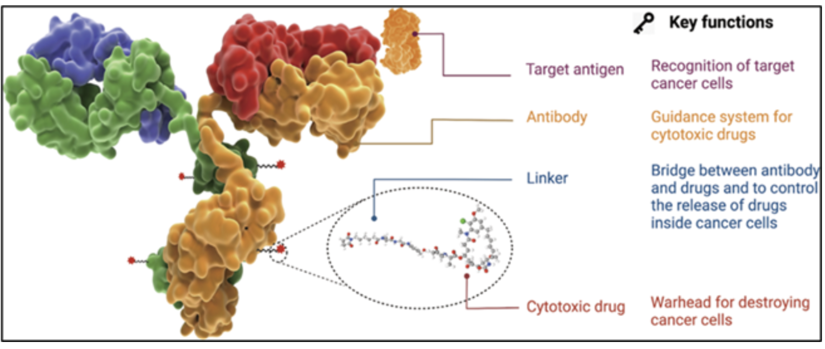
A typical ADC consists of three elements:
This design allows selective delivery of potent agents to tumor cells while minimizing off-target toxicity. However, the potency of the payload—often active at nanogram levels—requires stringent handling controls. Occupational Exposure Limits (OELs) are often <1 µg/m³, with payload handling being <10ng/m³ for the duration of the operation task. This profile drives the need for specialized containment and risk mitigation at every step of manufacturing. Importantly, the required containment performance can vary depending on the process phase—such as handling the pure payload in powder form versus when it is conjugated with mABs—necessitating a review and confirmation of equipment suitability at each stage.
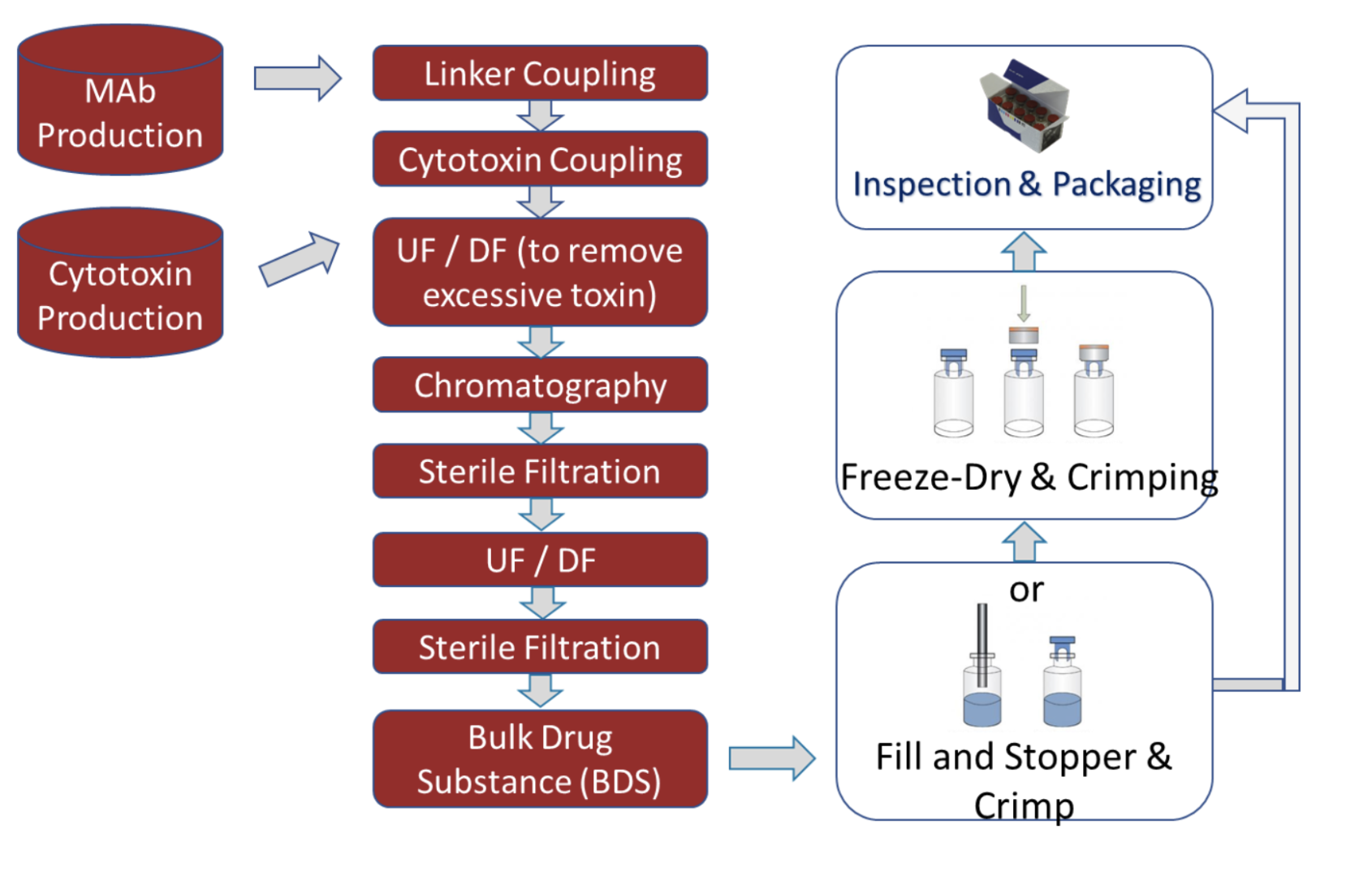
ADC production includes both Drug Substance (DS) and Drug Product (DP) workflows:
Each process step varies in terms of exposure risk (low to high) and influences facility design and containment strategy.
ADC facilities must accommodate varying batch sizes and process intensities as products progress through development.
Supporting Early-Stage ADC Process and Containment Design
Non-GMP Environment
Objective: Early conjugation chemistry optimization, formulation studies, and Drug-to-Antibody Ratio (DAR) characterization.
Emphasis: Exploratory testing, parameter screening, and process proof-of-concept under controlled containment.
Engineering Intent: Establish containment strategy, define process flow, and generate design data to support scale transition to pilot and kilo labs.
Bridging Process Development to Pilot Scale
Non-GMP Environment
Objective: Bridge PD to pilot scale; evaluate mixing, filtration, and transfer performance under contained conditions.
Emphasis: Establish process robustness, define operating ranges, and support early technology transfer.
Engineering Intent: Validate scale-up assumptions, confirm equipment design parameters, and guide the transition to GMP pilot or kilo labs.
Bridging Development to Clinical Manufacturing
GMP-Like or GMP Batches
Objective Support toxicology and early clinical studies; validate process scalability, containment performance, and automation strategy.
Emphasis: Process qualification, containment verification, and operator training under GMP-simulated conditions.
Engineering Intent: Confirm facility readiness, validate process control sequences, and generate data for full GMP clinical manufacturing transition.
Translating Process Design into Full GMP Manufacturing
cGMP Clinical & Commercial Operations
Objective: Support Clinical Phases I–III, process validation, and commercial launch manufacturing.
Emphasis: Full GMP compliance, automation, and implementation of advanced Process Analytical Technology (PAT).
Engineering Intent: Deliver robust, fully contained, and automated manufacturing environments that ensure safety, reproducibility, and regulatory compliance from clinical to commercial scale.
Single-use (SU) systems are favored throughout development and early clinical stages to reduce cleaning burden, lower cross-contamination risk, and accelerate changeovers. At larger scales, where throughput or process needs exceed SU capabilities, Wash-in-Place (WIP), Clean-In-Place (CIP) or Steam-in-Place (SIP) enabled stainless-steel systems are introduced. All systems are designed to facilitate closed processing wherever possible.
Drug Product operations—typically lyophilized sterile vials—are manual or semi-automated at small scale, transitioning to integrated fill/finish isolators at larger scale. Post-fill vial cleaning / decontamination ensures safe downstream handling, often performed using external vial washers or isolator-integrated decontamination systems (e.g., WFI spray, H₂O₂ vapor, or alcohol-based cleaning) to remove any potent drug residues from vial exteriors before inspection, labeling, and packaging
The overall containment strategy for ADC manufacturing must be guided by a comprehensive Process Hazard Analysis (PHA) as well as a Quality Risk Assessment for GMP operations. This analysis is essential for systematically evaluating the risks associated with handling highly potent and cytotoxic materials across all process steps, scales, and equipment configurations. The containment strategy must be tailored to address two primary objectives:
Personnel, Facility, and Environmental Protection: To prevent occupational exposure and unintentional environmental release, the containment approach must ensure that operators are protected from airborne or surface contact with potent compounds. This includes evaluating the need for engineered containment systems, personal protective equipment (PPE), ventilation controls, and waste handling protocols to maintain exposure levels well below the established Occupational Exposure Limit (OEL)—often as low as <10 ng/m³ for the duration of the operation task for OEB-5 compounds and below.
Product Quality and Cross-Contamination Control: To preserve product integrity and ensure regulatory compliance, the strategy must eliminate risks of cross-contamination between ADC payloads, intermediates, and final drug product. This requires careful consideration of process segregation, equipment design, cleaning validation, and airflow and pressure zoning, particularly in multi-product or campaign-based manufacturing environments.
The PHA should be multidisciplinary in scope, involving process engineering, occupational hygiene, quality assurance, and operations. It forms the foundation for selecting appropriate primary engineering controls, defining facility zoning, establishing cleaning and decontamination procedures, and identifying administrative safeguards. Ultimately, the containment strategy must balance risk reduction, operational efficiency, and compliance, while aligning with industry best practices and regulatory expectations for the safe manufacture of potent and sterile biologics such as Antibody-Drug Conjugates (ADCs). Typically, the containments design strategy consists of three protective layers as discussed below.
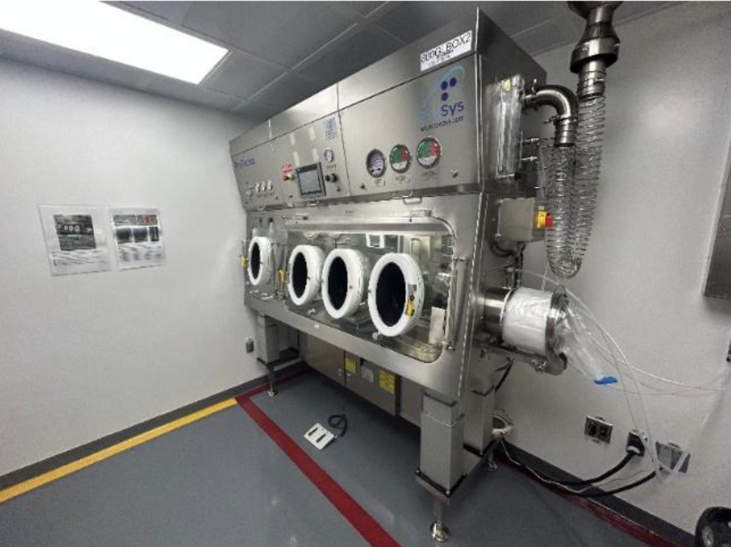
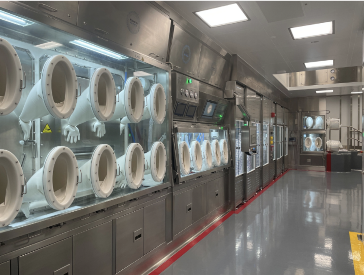
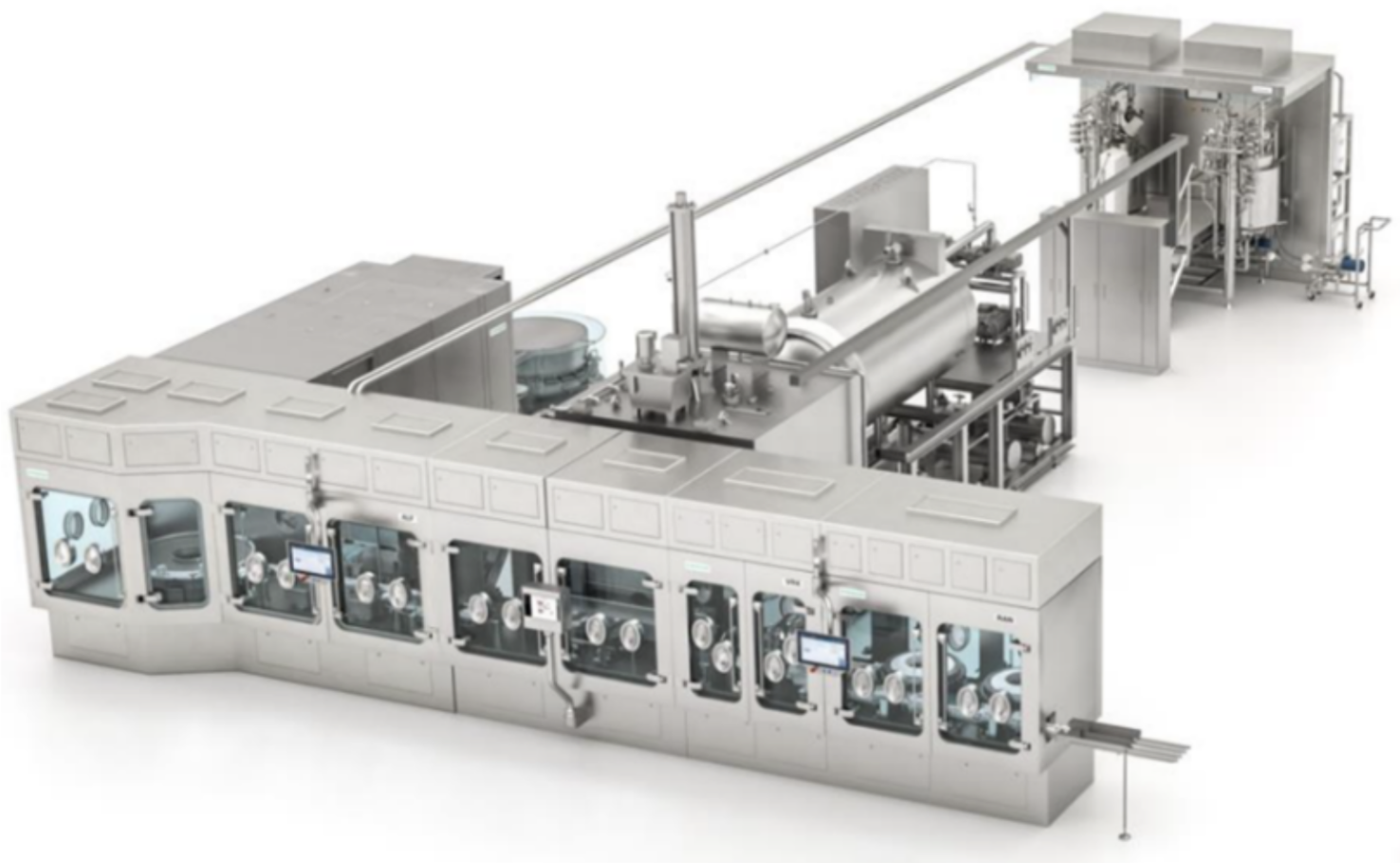
Solids Handling of Potent Material: In ADC manufacturing, all open handling of potent solids, such as cytotoxic payloads, is performed exclusively within high-containment isolators. These isolators are outfitted with double continuous liner systems, Rapid Transfer Ports (RTPs), and double Exhaust HEPA-filtered airflow to ensure personnel protection, product containment, and compliance with OEB-5 exposure limits. Material transfers between process steps—for example, from weigh-and-dispense operations to conjugation or formulation—are conducted using fully closed-system solutions. These include hermetically sealed transfer containers, alpha-beta canisters, and Containment Valves such as split butterfly valves (SBVs), which enable contained, dust-free transfer of potent solids between isolators, vessels, or rooms. Where applicable, single-use containment bags or sealed docking systems may be employed to further simplify cleaning requirements and reduce cross-contamination risks. These engineering controls are designed to minimize breach points and environmental release, ensuring robust containment throughout the material handling workflow while supporting cleaning efficiency and operational flexibility across clinical and GMP manufacturing scales.
Liquid Handling of Potent Material: Liquid handling operations in ADC manufacturing are designed as closed-system configurations to contain cytotoxic solutions and mitigate the risk of operator exposure. Transfers are typically executed through sealed, hard-piped connections or single-use tubing assemblies, routed between vessels and unit operations without breaking containment. Where flexible tubing or non-rigid containers are required—such as during sampling, bag transfers, or bulk fill operations—these activities are conducted within ventilated enclosures, such as fume hoods, biosafety cabinets or containment isolators, to provide secondary containment in the event of tubing failure, disconnection, or splash. For higher-volume or fixed installations, rigid stainless-steel vessels and hard-piped connections may be employed to support secure and repeatable liquid transfers.
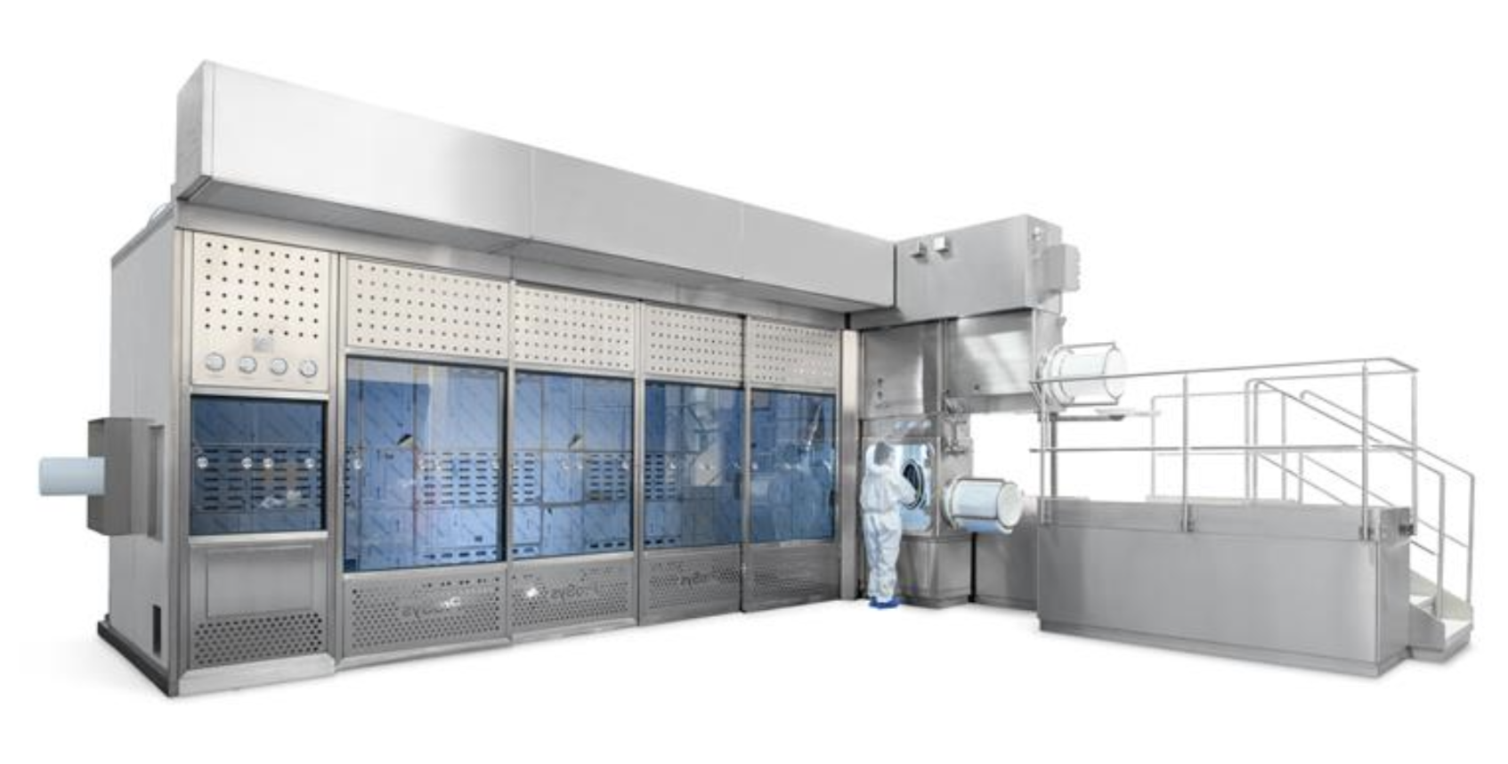
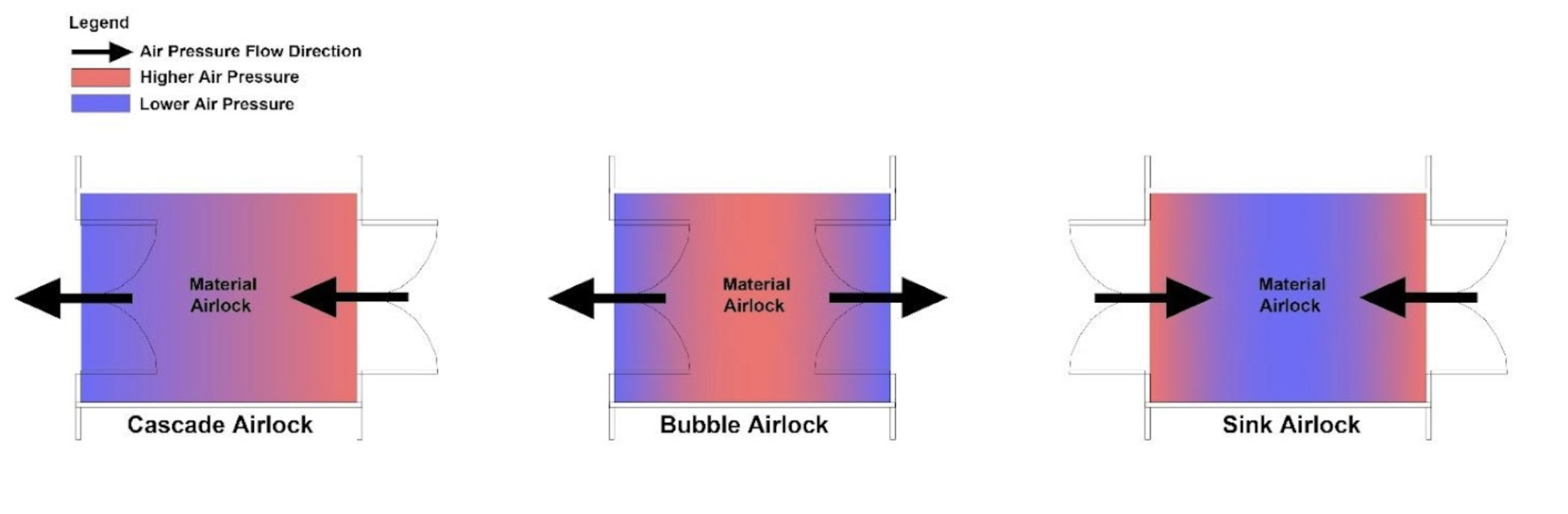
Secondary engineering controls serve as the next layer of defense in the containment hierarchy, designed to mitigate the risk of exposure in the event of a breach or failure of primary engineering controls (e.g., isolators, closed transfer systems). These controls are integrated into the room- and facility-level design and are critical for maintaining environmental safety, especially in OEB-5 manufacturing environments such as those used for ADC production. Key features of secondary containment systems may include (Figure 10):
Secondary engineering controls are particularly critical in multi-product or campaign-based ADC facilities, where product changeovers and material movements introduce additional containment challenges. These controls work in concert with primary engineering controls and administrative procedures to ensure a robust, multilayered containment strategy aligned with GMP, ISO cleanroom, and occupational hygiene standards.
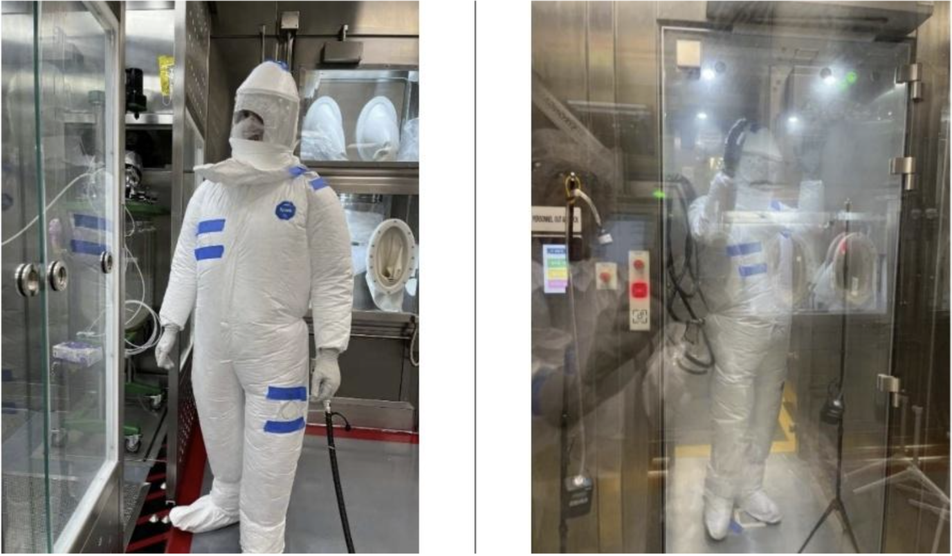
In the event of a breach in Secondary Engineering Controls, Tertiary Engineering and Administrative Controls serve as the final safeguard, relying on personnel protection and procedural measures.:
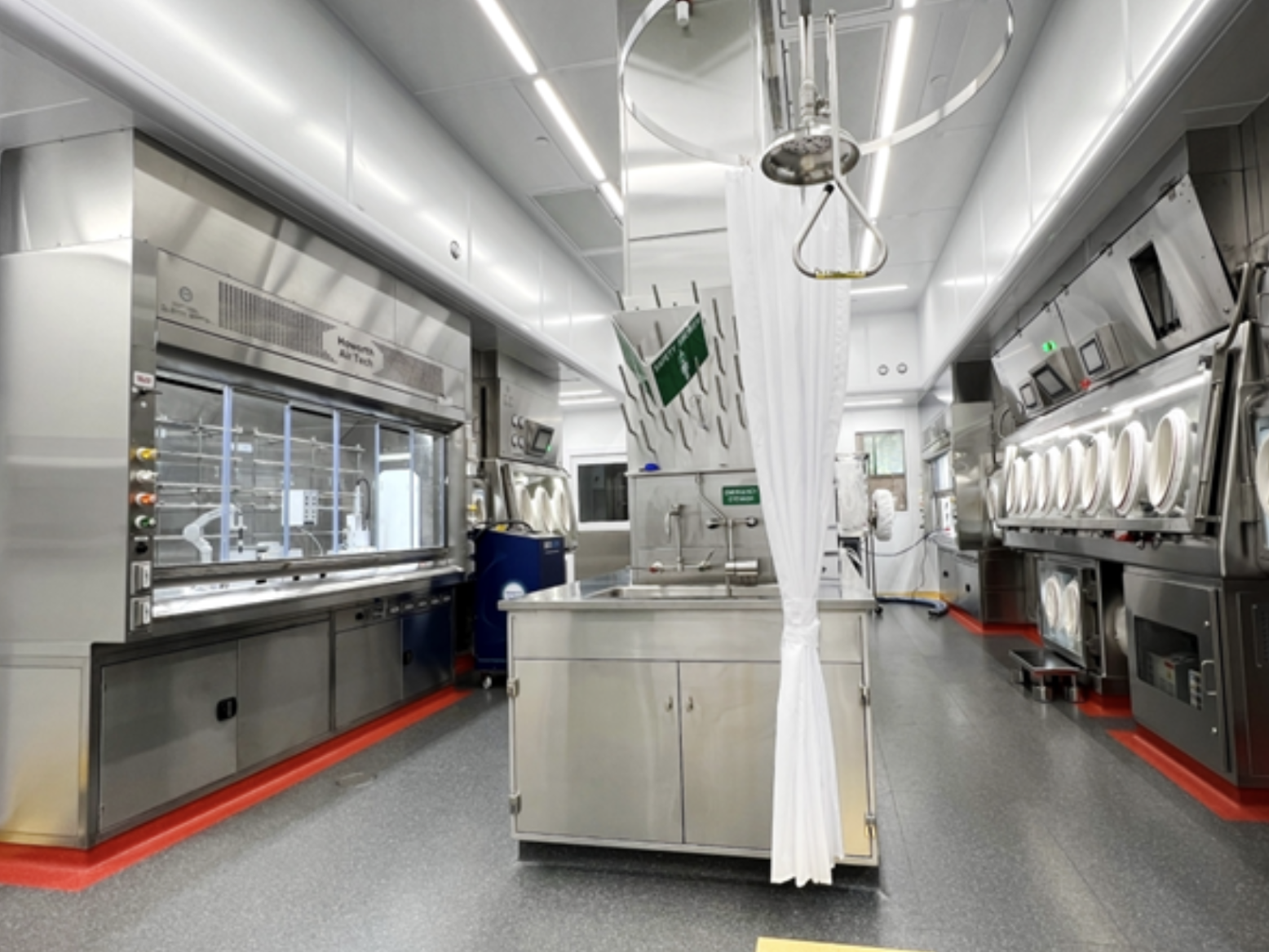
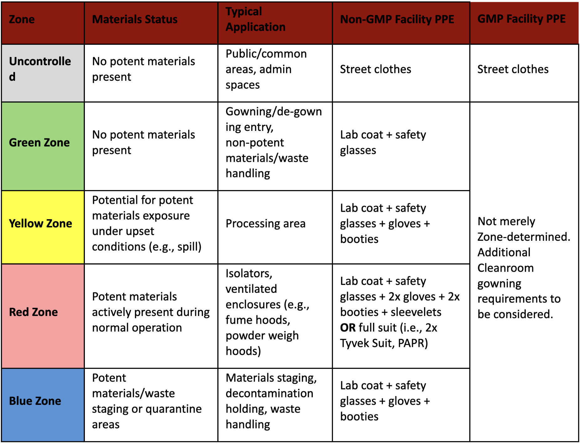
ADC processing spaces are divided into four distinct operating zones. Each zone is physically demarcated and is assigned to dedicated applications with associated PPE requirements. Operating zones (green/yellow/red/blue) may be defined with tailored PPE requirements and physical separation as described in the below table.
Automated Cleaning of Potents: Clean-in-Place (CIP) systems for potent compound–containing equipment with self-cleaning design are engineered to ensure effective decontamination while minimizing operator exposure and cross-contamination risks. These systems are engineered to prevent the cross-contamination risks commonly associated with traditional CIP setups used in conventional biologics manufacturing.
Manual Cleaning of Potents: For equipment and enclosures not compatible with Clean-in-Place (CIP) systems, validated manual cleaning procedures are implemented to ensure effective removal of potent residues. Surface swab samples are collected and analyzed in the laboratory to verify that cleanliness meets established acceptance limits.
ADC manufacturing produces large amounts of potent waste generated, primarily from tangential flow filtration (TFF), chromatography processes, and, where applicable, cleaning operations involving cytotoxic compounds.
Waste is segregated by type within the processing suite, including: potent / non-potent, solid / liquid, aqueous / solvent, etc., and handled in accordance with validated safe-disposal procedures.
Potent Liquid Waste is managed using closed primary containment systems—such as hard-piped vessels, single-use tubing, and transfer lines—and is pumped into dedicated waste tanks, totes, or disposable containers for controlled removal.
Potent Solid Waste including single-use materials like filters, tubing, wipes, and PPE contaminated with cytotoxic residues, is collected in hermetically sealable containers, double-bagged and treated as hazardous waste.
Waste Containers are all thoroughly wiped down and double-bagged prior to exiting the controlled processing area to mitigate external surface contamination.
Final Waste Storage occurs in designated hazardous waste holding areas, and removal from the facility is conducted by licensed third-party hazardous waste management specialists in compliance with regulatory requirements.
Effective material handling is critical to maintaining product quality, ensuring operator safety, and preventing cross-contamination in ADC manufacturing. Given the hazardous nature of cytotoxic payloads and the temperature sensitivity of biologic materials such as mAbs, ADC facilities must implement rigorous controls throughout the storage, staging, and internal movement of all materials.
Cytotoxic Payloads are received in rigid, double-contained packaging to prevent accidental release and operator exposure. These containers are transferred and stored exclusively in dedicated, negatively pressurized hazardous material storage areas equipped with HEPA-filtered exhaust systems.
Monoclonal Antibodies (mAbs) are temperature-sensitive biologics and are stored in validated cold storage units, typically maintained at 2–8 °C for short-term storage, or –20 to –80 °C for long-term preservation. Storage conditions are continuously monitored, with access controlled to preserve material integrity and traceability.
All materials entering the ADC manufacturing environment must comply with defined gowning, cleaning, and environmental monitoring procedures. Material flows are carefully separated from waste and personnel pathways to preserve unidirectional movement and prevent contamination across classified zones.
Manufacturing ADCs requires careful integration of containment, cleaning strategies, process flexibility, and facility design. Given the complexity of integrating specialized process equipment with high-containment systems, ergonomic workflow, and GMP facility infrastructure, engaging experienced professional support is essential to achieving a successful outcome. Proper planning and technical expertise can help ensure scalable, safe, and cost-effective solutions throughout the ADC development lifecycle.